Fluid Rendering Components
Fluid Renderer
The Fluid Renderer component is responsible for rendering a Fluid Simulation or a Fluid Simulation Static. This component is in charge of creating and rendering the necessary meshes and materials needed for displaying the assigned data. Users can customize the Fluid Renderer component to create their own rendering effects, similar to Water Surface and Lava Surface renderers.
Set Mode to Dynamic for a live solver, or Static for a bake. The inspector shows only one of those fields. See Baked Surface Playback to export and assign a bake.
| Property | Description |
|---|---|
| Debug Mode | Different fluid debugging modes that can be used in the editor. |
| Surface Properties | Properties that determine the mesh quality and the specific drawing mode of the fluid surface. This structure holds settings that control the visual fidelity and performance of the fluid surface mesh. This includes the specific method used to render the mesh, such as standard MeshRenderer, procedural drawing, GPULOD, or a specialized HDRP mode. |
| Fluid Material | The material to be used to render the fluid surface. This material is internally instantiated at runtime. The component copies the properties from the original material to the new instance, and then overrides or injects any necessary rendering requirements (e.g., shader keywords or properties) for the fluid simulation effects to function correctly. |
| Mode | Chooses whether this surface reads a live solver or a frozen bake. Dynamic uses a Fluid Simulation. Static uses a Fluid Simulation Static. The inspector shows only one field. |
| Simulation | The Fluid Simulation this renderer will draw. Visible when Mode is Dynamic. The renderer uses the simulation size and position. |
| Static Simulation | The Fluid Simulation Static this renderer will draw. Visible when Mode is Static. Assign a Surface Bake on that component. |
| Flow Mapping | The Fluid Flow Mapping component that this Fluid Renderer uses to visualize fluid currents and wakes. This component provides the necessary data to the fluid shader, which can be either a dedicated flow map texture (for dynamic UV-offsetting) or material parameters derived directly from the simulation’s velocity texture. This allows the fluid surface to depict accurate movement and flow. On a live simulation the layer can sit on the sim. On a static simulation assign it on this renderer and use Static or StaticFast. |
| Render Skirts | Renders downward skirts at the edges of the fluid surface. |
Fluid World Renderer
Fluid World Renderer draws multiple Fluid Simulation tiles as one continuous surface. Use it for open oceans, large lakes, and any scene where simulation is split across several domains but should look and behave like a single body of water (or other fluid type).
The component always renders with GPULOD. Each frame it gathers matching simulation tiles in the scene, composites their height, normal, terrain, foam, and flow data, and draws one world-scale surface from that combined result. You configure the footprint, material, channels, and optional ocean/detail-wave layers in the Inspector on this one object.
For water-specific rendering (underwater, caustics, reflections, foam on the world surface), use Water World Renderer instead. It extends this component with the same features as Water Surface on a per-tile Fluid Renderer.
Fluid Renderer vs Fluid World Renderer
Each Fluid Simulation can still have its own Fluid Renderer or Water Surface for local effects, debugging, or single-tile scenes. In a tiled open-world setup you typically rely on the world renderer for the visible surface and disable or omit per-tile renderers to avoid drawing the same water twice.
| Use Fluid Renderer | Use Fluid World Renderer |
|---|---|
| One simulation domain | Many simulation tiles in one view |
Any Render Mode (MeshRenderer, DrawMesh, GPULOD, HDRP Water) |
GPULOD only |
| Per-tile underwater, caustics, reflections via Water Surface | Multi-tile water features via Water World Renderer |
Setting up a tiled world
A typical multi-tile workflow looks like this:
- Place one Fluid Simulation per region. Align tiles in the scene so their domains meet edge to edge.
- On shared edges, set Side Border Settings to Neighbour and use the same Group ID so simulations stay connected. Grid Pos helps neighbour discovery; compositing itself follows each tile’s position and size in the scene.
- Add a Fluid World Renderer (or Water World Renderer) to the scene. Set Surface Properties Dimension to the XZ area you want the world surface to cover.
- Match Fluid Channels on the renderer and on each simulation you want included. See Fluid Channels in Setup for naming and masking.
- Enable ocean FFT in Ocean FFT Settings for large open-water swell. On Flow Fluid Simulation tiles, configure Ocean FFT Coupling so local shallow-water flow follows the ocean motion near coastlines.
- Optionally enable detail waves in Detail Wave Settings for small ripples on top of the composited surface. These are visual only and do not affect simulation or Fluid RigidBody physics.
Up to 32 simulation tiles can be composited at once. Fluid RigidBody buoyancy works across the combined surface when a world renderer is present; single-tile setups still use Read Back Height on the simulation instead.
The World sample is a complete example of this setup.
Which simulations are included
The renderer does not reference simulation objects directly. Any Fluid Simulation in the scene whose Fluid Channels overlap the renderer mask is drawn:
(renderer mask & simulation.fluidChannels) != 0
Use ~0 on both sides to include every channel. Use separate channel masks and separate world renderers when you want independent surfaces (for example one renderer for ocean water and another for lava).
General

| Property | Description |
|---|---|
| Fluid Channels | Bitmask of simulation channels included in the world atlas. A Fluid Simulation is packed when (renderer mask & simulation.fluidChannels) != 0.Use ~0 to include all channels, or 0 to pack nothing. |
| Fluid Material | The material to be used to render the fluid surface. This material is internally instantiated at runtime. The component copies the properties from the original material to the new instance, and then overrides or injects any necessary rendering requirements (e.g., shader keywords or world-atlas textures) for the fluid simulation effects to function correctly. |
Mesh Rendering
| Property | Description |
|---|---|
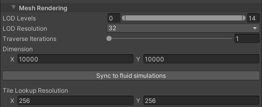
| Surface Properties | Properties that determine the mesh quality and the specific drawing mode of the fluid surface. This structure holds settings that control the visual fidelity and performance of the fluid surface mesh. World rendering uses GPULOD; set Render Properties to the XZ footprint used for GPULOD and shader sampling (see Mesh Rendering in the Inspector). |
| Tile Id Grid Resolution | Resolution of the world-space tile index texture (XZ) used by GPULOD and shaders to map positions to atlas tiles. Higher values improve lookup precision for large worlds at the cost of memory and sampling cost. |
| Debug Visualization | Different fluid debugging modes that can be used in the editor. Play Mode only. Uses shader FluidFrenzy/Debug/SimulationData (same family as Fluid Renderer).Height, normals, velocity (from the height/velocity atlas), UV, and LOD modes are supported for world-atlas rendering. |
Water World Renderer
Extension of Fluid World Renderer for multi-tile water: foam, underwater, current particles, wet lens, caustics, planar reflections, and screen-space reflections, mirroring Water Surface on Fluid Renderer. Configure underwater, current particles, wet lens, caustics, and surface reflections in the Water Rendering sections below.
Ocean FFT Settings
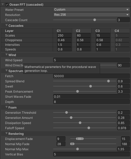
Settings for the cascaded ocean FFT on Fluid World Renderer. These control the JONSWAP spectrum, cascade layers, and distance fades used for large-scale open-water displacement. To apply that motion on the shallow-water solver, configure Ocean FFT Coupling on each Flow Fluid Simulation tile.
| Property | Description |
|---|---|
| Ocean Fft Enabled | Enables cascaded ocean FFT displacement (JONSWAP spectrum) on the world surface. When enabled, the renderer selects global cascade-count shader keywords and binds FFT data via shader globals. |
| Water Preset | A starting profile for the ocean waves. Pick a preset for quick results, or choose Custom and tune the fields yourself. Changing spectrum or cascade values switches back to Custom. |
| Resolution | Internal resolution of each wave layer. Higher values look sharper but use more GPU memory and time. |
| Cascade Count | How many wave size layers are active. C1 is the largest, longest waves. More layers add detail but cost more. Inactive layers are ignored at runtime. |
| Wind Speed | Wind speed in meters per second. Stronger wind builds taller, faster-moving waves. |
| Scales | World size in meters for each wave layer (C1-C4). C1 covers the largest area (open-ocean swell). Smaller values on later cascades add nearby chop and ripples. |
| Choppiness | Horizontal curling of each wave layer. Higher values make crests sharper and more displaced. Values are capped to avoid broken-looking folds. |
| Intensities | Height of each wave layer. Scales how tall each cascade moves the surface up and down. |
| Speeds | Animation speed of each wave layer. Multiplier on how fast each cascade moves over time. |
| Wind Direction | Wind direction in degrees. Controls which way the generated waves prefer to travel. |
| Fetch | How far the wind has blown over open water, in meters. Larger fetch builds longer, more developed swell. Use smaller values for bays, lakes, and rivers. |
| Spread Blend | Blend between wind chop and organized swell direction. Lower values spread waves in more directions. Higher values align waves with the wind. |
| Swell | Amount of long, rolling swell. Adds slower, larger motion on top of wind-driven waves. |
| Peak Enhancement | How peaked the largest waves are. Higher values sharpen wave crests in the spectrum. |
| Short Waves Fade | Softening of the smallest ripples. Reduces high-frequency shimmer. Raise slightly if the surface looks too noisy. |
| Depth | Average water depth in meters. Shallow water shortens wavelengths and changes wave shape. Use a low value near shores and rivers. |
| Generation Threshold | How much wave folding is needed before whitecaps appear. Lower values show foam on milder crests. Higher values require stronger breaking. |
| Generation Amount | Strength of fresh foam at breaking crests. Higher values inject foam faster where waves are actively breaking. |
| Dissipation Speed | How quickly existing foam fades away. Higher values remove foam faster once waves stop breaking. |
| Falloff Speed | How much leftover foam blends into neighboring texels. Higher values keep tighter streaks along crests. Lower values smear foam trails wider. This controls spatial spread, not fade over time. |
| Displacement Fade | Distance range where FFT waves fade out near the camera. X = start fading, Y = fully faded. Uses cascade distance units (not meters); finer layers fade closer than large swell. |
| Normal Mip Fade | Distance range where wave normals soften far from the camera. X = begin softening (meters), Y = full softening (meters). Helps distant ocean look smoother. |
| Normal Mip Max | Maximum softening applied to far-away wave normals. Works with Normal Mip Fade to reduce sparkly detail in the distance. |
| Vertical Bias | Vertical offset of the FFT ocean surface in world space. Raises or lowers the rendered ocean without moving the fluid simulation mesh. Also used when deciding if thin sim water should be hidden in favor of the ocean look. |
Surface Renderer
Surface Renderer defines a interface for rendering techniques aimed at height field surfaces. Implementing classes should provide specific algorithms and methods to visualize height maps and related surface data in different graphical contexts, such as terrain or fluid fields. This interface is designed to promote extensibility, allowing developers to introduce new rendering methods as needed while adhering to a standard approach for rendering surfaces. Currently there are three classes that extend this interface.
MeshRendererThe implementation using standard Mesh Renderer Surface components.MeshA simpler implementation using Mesh Surface.GPULODAn implementation using a GPU-accelerated LOD system: GPULOD Surface.
All classes implementing this interface must provide functionality to clean up resources by overriding the dipose method, ensuring that any graphics resources are properly disposed of.
Render Properties
Properties to be used to configure components that use Surface Renderer. These properties determine the mesh quality and rendering mode of the surface.
| Property | Description |
|---|---|
| Render Mode | The method used for generating and rendering the fluid surface geometry. - MeshRenderer Uses standard GameObjects with Mesh Renderer components. Best for simple setups where standard object culling is sufficient.- DrawMesh Uses Render Mesh to avoid GameObject overhead. Supports GPU Instancing.- GPULOD Draws the surface using a GPU-accelerated LOD system. Best for large-scale oceans or lakes. - HDRPWaterSurface Bridges the simulation data to a Unity HDRP Water Surface component (Requires HDRP). |
| Dimension | The total world-space size (X and Z) of the rendered surface. |
| Mesh Resolution | The vertex resolution of the surface’s base grid mesh. For the most accurate visualization, it is recommended to match this value to the source heightmap resolution. |
| Mesh Blocks | The number of subdivisions (blocks) to split the rendering mesh into along the X and Z axes. Subdividing the mesh improves GPU performance by allowing the camera to cull blocks that are outside the view frustum. |
| Lod Resolution | The vertex resolution of individual LOD patches when using GPULOD. |
| Traverse Iterations | The number of iterations the Quadtree traversal algorithm performs per frame when using GPULOD.Higher values resolve the surface quality faster during camera movement but may reduce performance. |
| Lod Min Max | The range of allowable LOD levels, where X is the minimum level and Y is the maximum level. |
| Hdrp Water Surface | Configuration settings for bridging this simulation’s data to an external HDRP Water Surface. |
Detail Wave Effect
This effect handles the small surface ripples (detail waves) for the fluid by managing GPU math for real-time waves or playing back pre-rendered textures.
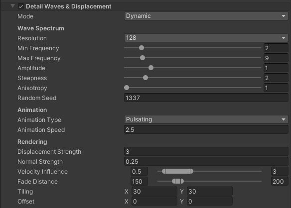
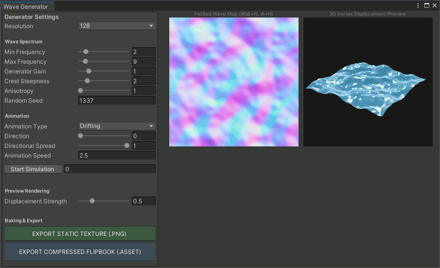
These ripples are purely visual and do not affect the actual fluid simulation, physics interactions, or buoyancy math. To save on GPU performance, you can bake these waves into static textures or flipbooks using the generator tool found at Window > Fluid Frenzy > Detail Wave Generator.
Detail Wave Settings
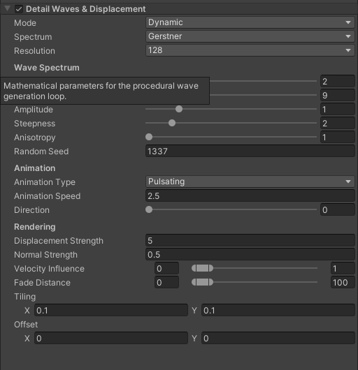
| Property | Description | |||
|---|---|---|---|---|
| Detail Waves Enabled | Enables procedural or baked detail waves on the world surface. These ripples are purely visual and do not affect the fluid simulation, physics, or buoyancy. |
|||
| Mode | Determines the method used to generate or display detail waves on the fluid surface. - Baked Uses a single static texture for maximum performance but lacks motion. - Flipbook Cycles through a pre-rendered texture array for smooth animation at a low GPU cost. - Dynamic Calculates procedural wave math in real-time for infinite variety at a higher performance cost. |
|||
| Resolution | The pixel dimensions of the generated wave texture. Gerstner supports any power-of-two up to 1024 for bakes / dynamic. FFT snaps to 64-512 only. |
|||
| Min Frequency | Defines the scale of the largest waves in the generated spectrum. Low values (1-2) create large, rolling swells. High values (5+) make the primary wave shapes much smaller and busier. |
|||
| Max Frequency | Defines the scale of the smallest ripples. Low values result in a smoother surface. High values add high-frequency micro-fidget and “noise” to the water surface. |
|||
| Amplitude | A global multiplier for the internal wave height math. This scales the wave spectrum before it is packed into the texture. Use this to push waves toward their maximum normalized height. |
|||
| Steepness | Determines the sharpness of the wave crests. 1.0 creates smooth, hilly waves. Higher values (up to 8.0) pinch the crests into sharp, aggressive peaks. |
|||
| Anisotropy | Stretches frequencies to create wind-streaks. 1 = Circular ripples, 10 = Long streaks |
|||
| Random Seed | The seed used to initialize the random layout of the wave pattern. Change this to get a different visual layout using the same settings. |
|||
| Animation Type | Determines if the waves bob in place or travel in direction. | |||
| Animation Speed | How fast the wave shapes change or travel. Higher values make the water look more energetic and wind-swept. |
|||
| Spectrum | Gerstner sum vs JONSWAP FFT (same packed height/normal texture). FFT requires a compute shader. | |||
| Wind Direction | The direction the waves travel (Only applies to Drifting mode). | Directional Spread | Controls the alignment of wave directions. 1.0 makes waves move in all directions (chaotic). 0.1 forces waves into organized, parallel rows. |
|
| Baked Texture | The texture asset used for displacement when in Baked mode. Expected format: Alpha channel for Height, RGB channels for Normals. |
|||
| Baked Texture Array | A sequence of wave frames stored as a compressed Texture2DArray. | |||
| Flipbook FPS | The speed at which the flipbook cycles through frames. | |||
| Displacement Strength | World-space peak height in metres applied to the packed detail-wave map. Dynamic Gerstner and FFT pack height so that a value of 1 is approximately a 1 metre peak (with Generator Gain at 1). Lighting normals use the same scale. |
|||
| Normal Strength | Extra multiplier on packed detail-wave normals. 1 matches the displaced heightfield when Tile World Size is aligned with Tiling. Lower to soften lighting without changing mesh displacement. |
|||
| Velocity Influence | X = Minimum strength at 0 velocity. Y = Maximum strength multiplier. | |||
| Fade Distance | Distance (Start, End) in meters where detail waves fade out to prevent shimmering and tiling artifacts. | |||
| Tiling | How many times the wave pattern repeats across the surface area. | |||
| Offset | A manual offset to scroll or shift the wave pattern. | |||
| Directional Spread | Controls the alignment of wave directions. 1.0 makes waves move in all directions (chaotic). 0.1 forces waves into organized, parallel rows. |
HDRP Water Surface Properties
Contains settings used to bridge the fluid simulation data to the Unity HDRP Water System.
| Property | Description |
|---|---|
| Target Water Surface | The target HDRP Water System component the simulation is to be applied. (Requires HDRP package). |
| Amplitude | Controls the maximum amplitude of the Fluid Simulation used to encode/decode the height to/from 0-1 range |
| Large Current | Controls the weight that the Fluid Simulation’s velocity should be applied to the Large Current waves of the HDRP Water System. |
| Ripples | Controls the weight that the Fluid Simulation’s velocity should be applied to the Rupples of the HDRP Water System. |
| Mesh Resolution | The vertex resolution of the surface’s base grid mesh. |
| Dimension | The total world-space size (X and Z) of the rendered surface. |
| Height Scale | The scale that will be applied to the height value in the surface’s height field. |
| Max Height | The maximum height the surface will be. This is used for the culling bounds of the meshes. |
| Heightmap Mask | Specifies which channels of the heightmap to read 1 is read, 0 is ignore. The result is accumulated with the following formula: dot(heightTexel, heightmapMask) |
| Lod Min Max | The minimum and maximum LOD levels that can be selected for the surface. lodMinMax.x(min) lodMinMax.y(max) |
Water Rendering
Water Surface
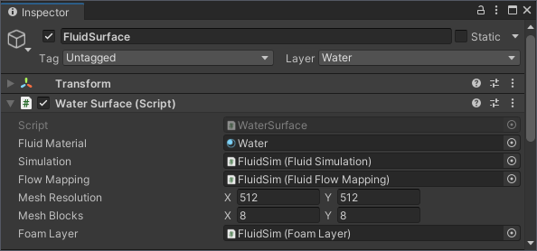
The Water Surface is an extension of the Fluid Renderer component that renders all things water like Foam Layer, Underwater Effect visuals, Current Particles, Wet Lens Effect, absorption, and scattering. It does this by assigning the active rendering layers to its surface material and using the underwater settings. It can draw a live Fluid Simulation or a Fluid Simulation Static. Set Mode on the renderer. See Baked Surface Playback.
Underwater, current particles, wet lens, caustics, planar reflections, and screen-space reflections use the same settings on Water Surface and Water World Renderer. See Underwater Settings, Current Particle Settings, Wet Lens Settings, Caustics Settings, and Surface Reflections below.
Underwater Effect
The Underwater Effect module renders the visuals you see when the camera goes underwater. It is supported in all render pipelines.
It uses the same simulation math as the water surface to ensure the underwater volume matches the waves perfectly. However it has its own independent visual settings, allowing you to style the underwater atmosphere separately from the surface itself.
This distinction is useful for gameplay as you can make the underwater view clearer or brighter than the surface to help players see further. The effect handles features like light absorption, fog scattering, and directional lighting to create the underwater atmosphere.
Underwater Settings
Settings for all configurable visual parameters of the Underwater Effect. This class defines how light interacts with the water volume, including absorption rates, scattering colors, and the appearance of the surface meniscus.
| Property | Description |
|---|---|
| Under Water Enabled | Controls whether the Underwater Effect is currently enabled. |
Absorption
| Property | Description |
|---|---|
| Color | The base transmission color of the water (Physical mode). This defines the color of the water as light passes through it. Brighter colors make the water look clear, while darker colors make the water look thick and deep. This works with the absorption depth scale to decide how much the scene behind the water is tinted. |
| Absorption Depth Scale | Controls the rate at which light is absorbed as it travels through the water. Higher values result in darker water where light cannot penetrate as deeply. This scaling factor applies to the exponential decay of the absorption color. |
| Absorption Limits | Clamps the calculated absorption to a specific range (Min, Max). Useful for preventing the water from becoming completely black at extreme depths or ensuring a minimum amount of visibility. |
| Color | The color of the light scattered within the water volume (subsurface scattering/fog color). Defines the color of the fog when light illuminates the water. Usually a bright cyan or teal for tropical water, or a murky green/brown for swamps. |
| Ambient Intensity | The base ambient contribution to the scattering effect, independent of direct lighting. Higher values cause the underwater fog to glow brightly even in shadows or when facing away from the sun. Lower values rely purely on direct sunlight for illumination. |
| Total Intensity | A global multiplier for the overall scattering intensity. Higher values create a dense, opaque volumetric fog. Lower values make the scattering very subtle, preserving the clarity of the absorption color. |
Meniscus(Water Line)
| Property | Description |
|---|---|
| Meniscus Thickness | The vertical thickness of the meniscus line on the camera lens (in centimeters). Simulates water clinging to the camera glass. Higher values create a thicker, more prominent droplet band at the waterline. Set to 0 to completely disable the meniscus effect. |
| Darkness | Controls the intensity/darkness of the meniscus line effect. Low values give the band a subtle, colorful tint matching the water color. High values simulate a physically thick droplet that blocks incoming light, creating a dark rim. |
| Refraction Bulge | Controls the refraction strength (optical distortion) of the meniscus droplet. Higher values bend the background pixels (Snell’s Law), causing extreme lensing and total internal reflection at the edges. Lower values look like flat, undisrupted glass, Negative values intert the refraction. |
| Reflectivity | The base reflectivity (Fresnel R0) of the wet meniscus lens. Higher values make the droplet highly reflective (mirror-like), reflecting more of the skybox/environment probe. Lower values keep the droplet mostly transparent. |
| Specular Intensity | Controls the brightness of the directional light specular glint on the meniscus. Higher values create a bright sun highlight when the camera looks towards the directional light at the waterline. Lower values dull the highlight. |
| Specular Power | Controls the sharpness and focus of the specular glint on the meniscus. Lower values (e.g., 16-64) spread the sun’s reflection out into a wide, wet smear across the lens. Higher values (e.g., 256-512) tighten the highlight into a microscopic, sharp pinpoint. |
| Chromatic Dispersion | Splits the RGB light (chromatic aberration) when refracting through the meniscus droplet. When enabled, the droplet samples three slightly different indices of refraction, causing a prismatic rainbow fringing effect at the edges of the water band. |
Scattering (Fog)
| Property | Description |
|---|---|
| Body Scattering | Sun scatter on flat wave troughs. |
| Tip Scattering | Sun scatter on wave crests. |
| Height Scattering | Ambient height term scale (matches surface Height Scattering). |
| Displacement Scattering | Ambient chop term scale (matches surface Displacement Scattering). |
| Scattering Wave Height | Reference wave height for ambient scatter terms (matches surface Scattering Wave Height). |
Volumetric Lighting
Screen-space underwater volumetric light shafts (godrays) for URP and Built-in. When enabled on Under Water Settings, the system raymarches the water column into a low-resolution buffer that Underwater Effect composites over the scene.
The effect follows the main directional light and can be modulated by shadow casters, temporal denoise, caustics-driven shaft breakup, and a post-resolve blur. Tune quality with sample count and buffer resolution.
| Property | Description |
|---|---|
| Enable | Raymarches the underwater volume with the main light to create godrays / light shafts. |
| Intensity | Brightness of the volumetric light shafts. |
| Anisotropy | How tightly the shafts concentrate toward the sun. Higher values make sharper godrays. Lower values spread the glow more widely. |
| Density | How much light scatters along each raymarch sample. |
| Sample Count | Number of raymarch steps. Higher is smoother but more expensive. Compiled as a shader keyword so the march loop can unroll. |
| Resolution | Buffer size relative to the screen. Quarter is cheapest. Half is sharper. Full matches the screen and costs the most. |
| Use Shadows | Modulate the shafts with the main light shadow map so occluders cast volumetric shadows. |
| Temporal Denoise | How much of the previous frame to reuse when cleaning up dither noise from the low sample count. Higher values look smoother but take longer to catch up when the lighting changes. Set to 0 to disable temporal reuse. |
| Shaft Strength | Carves wave-driven beams out of the shafts instead of a smooth glow. Reuses this surface’s caustics texture and tiling, projected up the light direction, so the beams in the water and the caustics on the seafloor are the same pattern. Set to 0 to leave the shafts shaped only by shadow casters. |
| Shadow Breakup | How strongly geometric shadow shafts break into filaments near occluder edges. Set to 0 for clean shadow-map shafts. |
| Breakup Scale | World scale of the breakup pattern. Higher values make finer filaments. |
| Breakup Speed | How fast the breakup pattern scrolls. |
| Blur Radius | Gaussian blur radius in texels, applied after resolve for display only. Softens leftover sparkle from the low sample count without smearing the temporal history. Set to 0 to disable. |
Current Particles
Current Particles draw additive current wisps and foam bubbles in the water volume. It is supported in all render pipelines.
Positions stay locked in the world inside a radius around the camera; you move through them. Wisps are current-aligned glitter ribbons in fast water. Bubbles rise through aerated foam and follow the flow. The effect is visible from above and below the surface.
Enable it on any Water Surface or Water World Renderer. It is independent of Underwater Effect: turning underwater off does not hide the particles. Draw happens in Play Mode, after the underwater pass when that pass also runs.
This feature requires compute shaders. See Feature Support.
Current Particle Settings
Settings for current-aligned wisps and aerated bubbles in the water volume.
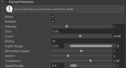
| Property | Description |
|---|---|
| Current Particles Enabled | Controls whether current wisps and foam bubbles are drawn in the water volume. |
| Wisps | Current-aligned glitter streaks in fast water. |
| Bubbles | Rising air bubbles in aerated, foamy water. |
| Intensity | Brightness of wisps and bubbles. |
| Size | Wisp thickness and bubble radius, in meters. |
| Count | How many particles to draw around the camera. Higher is denser and more expensive. Each slot can emit a wisp ribbon and a fan of bubbles. |
| Radius | How far from the camera particles can appear, in meters. Positions stay locked in the world; you move through them. Replicas recycle at the wrap-box faces. |
| Depth Range | Depth below the surface in meters. Min is fully visible, Max is where they fade out. |
| Movement Speed | How fast wisps and bubbles travel along the current. 1 is the default look. Uses a hashed clock, not live sim speed × elapsed time (that runs backward when the current wobbles). |
| Stretch | How long wisps run along the current when the flow is fast. |
| Turbulence | How much each wisp snakes up, down, and sideways along its length. Inspector 0–1 remaps in the shader so 1 is a moderate meander. |
| Speed Range | Current speed in m/s. Min is when wisps start to appear, Max is when they are fully visible. |
Wet Lens Effect
The Wet Lens Effect module renders leftover water on the camera after you leave the fluid. It is supported in all render pipelines.
While the camera is underwater the lens gets wet. After you surface, a sheet of water drains down the glass and leftover drops stay behind, bending the view until they dry off.
Enable it on any Water Surface or Water World Renderer. Only one pass is drawn per camera. Settings come from the water the camera is inside, then the last water that wet the camera. The lens never shows water that did not get wet, and the effect is hidden while you are still underwater.
Wet Lens Settings
Settings for all configurable visual parameters of the Wet Lens Effect. This class defines leftover water on the camera lens: how long it takes to dry, the draining film, and baked drops.
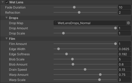
| Property | Description |
|---|---|
| Wet Lens Enabled | Controls whether leftover water is drawn on the camera after leaving this surface. Only one pass is drawn per camera. Enabling wet lens on any visible water surface or world renderer is enough. |
| Fade Duration | How long leftover wetness takes to dry off after leaving the water. Higher values keep the lens wet for longer after you surface. Lower values dry the film and drops off quickly. |
| Refraction Strength | How hard the film and drops bend the view. Higher values make the leftover water look thicker and more distorting. Lower values keep a subtler wet-glass look. |
Drops
| Property | Description |
|---|---|
| Drop Map | Texture that places leftover water drops on the lens. Height is stored in the alpha channel. Leave empty to hide drops. |
| Drop Amount | How strongly the baked drops refract (0 = none). At 0 the drops are hidden. At 1 they fully bend the view. Drops only appear where the film has receded, and only on a lens that got wet. |
| Drop Scale | Size of the baked drop texture on the lens. Higher = larger drops. Lower values tile the drop map more, so you see more, smaller drops. Higher values enlarge the same pattern. |
Film
| Property | Description |
|---|---|
| Film Amount | Strength of the water blobs sitting on the wet part of the lens (0 = drops only). At 0 you only see leftover drops. At 1 a sheet of blobs covers the wet lens and drains away as it dries. |
| Edge Width | How thick the blob rims are (0 = thin meniscus, 1 = a wider rim). At 0 the edge is a tight meniscus around each blob. At 1 the rim is wider and more spread out. |
| Edge Softness | How rounded the rim is. 0 = a harder cut, 1 = a fully rounded falloff. Low values give a sharper blob outline. High values round the rim so the sheet looks more like a smooth droplet. |
| Blob Scale | Size of the blobs. Lower = fewer, fatter blobs. Lower values merge the leftover water into larger blobs. Higher values break it into a finer, more detailed sheet. |
| Blob Amount | How strongly the noise breaks the boundary into blobs. At 0 the leftover water is a smoother sheet. Higher values chew the edges into irregular blobs. |
| Drain Speed | How fast the blobs creep down the lens. Higher values make the leftover sheet sag and drain faster. At 0 the blobs stay put while they fade. |
| Warp Amount | Interior refraction through the film (0 = flat sheet). At 0 the blob interiors are a flat sheet of water. Higher values add ripples through the middle of the film. |
| Warp Scale | Size of the interior warp. Lower = larger ripples. Lower values stretch the interior ripples. Higher values pack them tighter across the film. |
Caustics Effect
Caustics is an option on the Water Surface that simulates the shifting light patterns projected onto the seafloor and submerged objects.
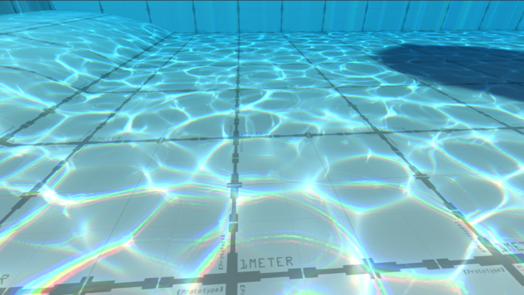
To keep performance high, the system uses a fast approximation rather than trying to calculate physically accurate light paths. It combines an animated texture sequence with procedural highlights that are tied to the surface wave curvature, ensuring the light patterns always match the motion of the water above.
The effect works directly with the Fluid Simulation, meaning it uses the same flow mapping as the surface itself. If the water is flowing or swirling, the caustics will follow that same movement. You can also enable triplanar projection to prevent the patterns from stretching or smearing on vertical surfaces like underwater cliffs or steep walls.
It also accounts for surface conditions for example, Foam Masking can be used to soften or dim the light patterns in areas where thick foam would naturally scatter the light. To keep transitions smooth, the effect uses depth fading to blend the patterns in and out based on how far they are from the surface, preventing them from looking too sharp at the shoreline or in very deep water.
Caustics Settings
Settings for all configurable visual parameters of the Caustics Effect. This class defines animated light patterns projected underwater, wave-driven highlights, and global visibility attenuation.
| Property | Description |
|---|---|
| Caustics Enabled | Controls whether the Caustics Effect is currently enabled. |
Texture Projection
You can use these settings to customize the look of the animated texture patterns, including how fast they move, how they warp with the waves, and whether they use triplanar mapping to stay consistent on vertical walls.
| Property | Description |
|---|---|
| Animation FPS | The playback speed of the animated caustics texture sequence. Defines how many frames per second the texture advances. Higher values result in faster, smoother motion. |
| Tiling | Controls the scale of the projected caustics pattern. Higher values increase the tiling frequency, making the pattern appear smaller and more dense across the environment. |
| Triplanar Projection | Enables triplanar projection to prevent texture stretching on vertical surfaces. Projects the texture from three orthogonal axes (X, Y, Z) instead of a single top-down projection. Essential for maintaining pattern consistency on cliffs, walls, and steep underwater terrain. |
| Wave UV Distortion | The strength of the UV distortion applied to the caustics based on surface wave normals. Simulates refractive warping by shifting the texture coordinates relative to the waves above. |
| Texture Intensity | The brightness multiplier for the projected caustics texture. An independent scalar specifically for the animated texture component of the effect. Zero disables the Fluid Render Pipeline shader variant (no flipbook samples). |
| Channel Mask | Defines which texture color channels contribute to the final caustics pattern. Useful for isolating specific channels in packed textures. |
| Chromatic Aberration | The strength of the color splitting effect at the edges of the caustics. Simulates light dispersion (prismatic effect), creating rainbow-like fringing around high-contrast areas of the pattern. |
Wave Highlights
These properties control procedural glints calculated directly from the surface waves, allowing you to adjust the intensity and sharpness of the light streaks hitting the seafloor.
| Property | Description |
|---|---|
| Wave Intensity | The brightness of the procedural glints generated by surface wave curvature. Unlike the texture projection, these highlights are calculated analytically from wave refraction to provide a direct link between the surface and the seafloor. |
| Wave Sharpness | Controls the focus and size of the procedural wave highlights. Higher values result in sharper, thinner glints (lensing effect), while lower values create broader, softer highlights. |
Global Settings
This section handles the overall strength and blending of the effect, including how it reacts to shadows and foam, and how it fades out as the water depth increases.
| Property | Description |
|---|---|
| Global Intensity | A multiplier for all caustic lighting contributions. Scales both the texture projection and the procedural wave highlights simultaneously. |
| Darkness | Controls how much the sea floor is darkened in the areas between light patterns. Increasing this value darkens the “caustic shadows,” making the bright light patterns appear more high-contrast and prominent. |
| Shadow Intensity | Controls the visibility of caustics within areas shadowed by external light sources. A value of 0 makes caustics completely invisible in shadow, while a value of 1 allows them to remain fully visible. |
| Surface Fade-In | Defines the depth range near the surface where the caustics begin to appear. The X value represents the depth where the effect starts, and the Y value is where it reaches full intensity. This prevents visual “popping” at the water line. |
| Depth Fade-Out | Defines the depth range where the caustics gradually disappear as light is absorbed. The X value is the depth where fading begins, and the Y value is the depth where caustics are completely extinguished. |
| Foam Masking | Controls how much surface foam occludes the caustics on the seafloor. Simulates the diffusive nature of bubbles. Thick foam scatters light, preventing sharp caustics from forming and casting a soft shadow on the environment below. |
| Half Resolution | Renders caustics at half screen resolution and upsamples before compositing. Large GPU win; slightly softer patterns. |
Surface Reflections
Surface Reflections are settings on Water Surface and Water World Renderer that add real-time reflections on top of reflection probes.
Fluid Frenzy supports two complementary techniques:
- Planar Reflections render the scene from a mirrored camera flipped around the water plane. This gives accurate reflections for geometry above the water but costs an extra camera pass.
- Screen Space Reflections (SSR) ray march the rendered scene color buffer to find reflected pixels (Built-in and URP). SSR is cheaper than a full planar camera for many scenes and can be combined with planar reflections.
The reflection plane follows fluid simulation height, with optional smoothing (Smooth Position) to reduce jitter from small waves.
Note: Planar and screen-space reflections require the water material to sample them. On the material (Water Shader and related variants), set Surface Reflections to match the techniques you enable here.
Note: HDRP does not use these settings in the water shader; HDRP renders reflections through its pipeline.
Planar Reflections
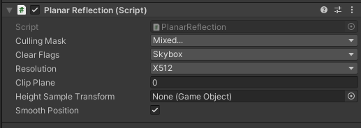
Planar reflections capture the scene from a mirrored camera and blend the result over reflection probes.
| Property | Description |
|---|---|
| Use Planar Reflections | Renders a mirrored camera reflection texture blended over probe reflections. |
| Resolution | The quality/resolution of the generated planar reflection texture. |
| Culling Mask | Which layers the planar reflection camera renders. Excludes Unity’s builtin Water layer (index 4) so the water surface is not reflected in itself. |
| Clear Flags | What to display in empty areas of the planar reflection’s view (e.g., Skybox, Solid Color). |
| Clip Plane | A vertical offset to apply to the reflection plane. This can be used to prevent clipping artifacts with the water surface. |
| Smooth Position | Smoothes the reflection plane’s height and position over multiple frames to prevent jittering caused by rapid fluid simulation updates. |
| Smooth Speed | How fast the reflection plane adapts to water height changes. Lower values result in smoother, slower transitions. |
| Snap Threshold | The height difference threshold at which the reflection plane instantly snaps to the new height instead of smoothly transitioning. |
| Renderer ID | SRP Renderer to use for the planar reflection pass. Use this to select a cheaper render pass for the reflection camera. |
| Render Shadows | Controls shadow map rendering for the planar reflection camera (URP only). |
| Shadow Quality | Controls shadow rendering in the reflection (BiRP Only). |
Screen Space Reflections
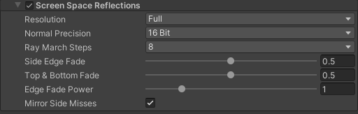
Screen Space Reflections trace reflected rays in screen space against the fluid depth prepass and a surface-normal prepass written for water pixels. The pass runs in Fluid Render Pipeline after the fluid prepass (Built-in / URP). SSR is one frame behind the scene color it samples, which is typical for screen-space techniques.
When multiple water surfaces are visible, the renderer picks the SSR settings from the surface with the highest enabled resolution.
| Property | Description |
|---|---|
| Use Screen Space Reflections | Ray marches the scene color buffer for reflections (BiRP / URP). Can be combined with planar reflections. |
| Resolution | Screen-space reflection buffer resolution relative to the camera. Quarter is cheapest. Half is sharper. Full matches the screen and costs the most. |
| Normal Precision | Bit depth of the octahedral surface normal prepass written for SSR. 8 bit is usually fine when the water has a lot of small wave detail. The reflection ray does not track fine normal changes very closely anyway so you save prepass bandwidth. Use 16 bit if reflections look banded or stepped. |
| Ray March Steps | Number of iterative ray march steps used to find reflected scene color. Higher values improve accuracy on steep reflections at a small GPU cost. Compiled as a shader keyword so the march loop can unroll. |
| Side Edge Fade | Width of the SSR fade at the left and right screen edges. 0 disables. Higher values fade sooner and still reach zero at the edge. |
| Top & Bottom Fade | Width of the SSR fade at the top and bottom screen edges. 0 disables. Higher values fade sooner and still reach zero at the edge. |
| Edge Fade Power | Exponent applied to the SSR edge fade curve. 1 is linear. Higher values fade reflections out faster near screen edges. |
| Mirror Side Misses | When a reflected ray misses left or right of the screen, fold the sample UV horizontally instead of falling back to probes. |
Fluid Decal Renderer
Fluid Decal Renderer stamps a texture onto visible fluid surfaces (water or lava) inside a world-space projector box.
The component does not use a mesh renderer. Each projector submits a procedural cube draw in LateUpdate using Graphics.RenderPrimitives, the same path as Fluid Particle System. The shader resolves the fluid surface per pixel using the fluid depth prepass (_FluidDepthRT), scene depth rejection, and optional velocity-driven flow mapping from the bound simulation.
The projector binds to the nearest Water World Renderer, Water Surface, or Lava Surface at its position. Assign a material using FluidFrenzy/FluidDecal or FluidFrenzy/FluidDecalLit (URP/BiRP), or the HDRP Shader Graph variants under FluidFrenzy/HDRP/Decal. Flow mapping is controlled on this component, not on the material.
Sort order relative to water and other transparents is controlled by the decal material Render Queue (default Geometry+512, queue value 2512). Raise or lower the queue on the material if decals draw in the wrong order.
Projector
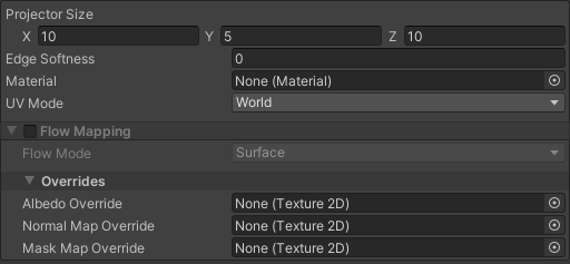
| Property | Description |
|---|---|
| Size | World-space size of the projector bounds. The selected shape is inscribed in this box. Height is always Size Y. |
| Edge Softness | World-space distance from the horizontal silhouette where opacity reaches 1. Steep falloff toward the boundary. 0 = hard cutoff. |
| Material | Material used to render the decal. URP/BiRP: FluidFrenzy/FluidDecal or FluidFrenzy/FluidDecalLit. HDRP: Shader Graphs under FluidFrenzy/HDRP/Decal. |
| Uv Mode | How decal texture tiling is applied across the projector box. - World Tiling is repeats per world unit. (1,1) = one tile per meter; (1/size, 1/size) = one tile across the box. - Projector Texture stretches 0..1 across the horizontal extent of the box. |
Flow Mapping
| Property | Description |
|---|---|
| Use Flow Mapping | When enabled, the decal texture advects with fluid velocity using the same flow-mapping modes as the surface shader. When disabled, the texture uses projector UV (0..1 across the box); use material Tiling/Offset to repeat. |
| Flow Mode | How the decal texture moves when flow mapping is enabled. - Surface Multi-phase crossfade matching the water material. Best for seamless tileable textures. - Drift Integrates fluid velocity and slides the stamp downstream. Requires Height & Velocity readback on the simulation, or a packed world atlas; otherwise Surface is used. |
Note: Drift needs Height & Velocity readback on the fluid simulation, or a packed world atlas. If neither is available, the projector uses Surface flow mapping instead.
Overrides
Optional per-projector texture overrides. When set, these replace the matching slots on the assigned material for this projector only.
| Property | Description |
|---|---|
| Albedo Texture | Optional albedo override. When set, replaces the material _MainTex for this projector via a property block. |
| Normal Map | Optional normal map override for FluidDecalLit. When set, replaces the material _BumpMap for this projector. |
| Mask Map | Optional mask map override for FluidDecalLit. Green = occlusion, blue = height, alpha = smoothness. When set, replaces the material _MaskMap for this projector. |
Lava
Lava Surface
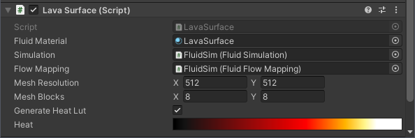
Lava Surface is an extension of the Fluid Renderer component that specifically deals with rendering lava-related elements of the fluid simulation. It can draw a live Fluid Simulation or a Fluid Simulation Static. Set Mode on the renderer. See Baked Surface Playback.
This component adds specific lava rendering features, such as heat and emissive color gradients, by generating and applying a custom Heat Look-Up Texture (LUT).
The LUT is procedurally generated from the Heat gradient field and is assigned to the Fluid Material. This allows the lava’s emissive color and heat visual effect to be determined dynamically by factors like the lava’s velocity or age.
| Property | Description |
|---|---|
| Under Lava Enabled | When enabled, the Under Lava Effect applies a depth-based tint while the camera is inside this lava volume. |
| Under Lava Settings | Tunables for the under-lava volume tint (absorption only). |
| Generate Heat Lut | If enabled, the Heat gradient will be used to procedurally generate a Heat LUT that overrides the existing LUT on the Fluid Renderer. |
| Heat | The Gradient used to define the heat/color transition for the lava. The color samples are mapped from Cold Lava (Left side of the gradient) to Hot Lava (Right side of the gradient). |
Under Lava Effect
Renders a depth-based tint when the camera is inside a Lava Surface volume, using the same mask and depth data as the underwater effect, with an optional surface band (meniscus-style thickness).
Under Lava Settings
| Property | Description |
|---|---|
| Composite Mode | Chooses how the under-lava pass blends the volume with the scene. Options include: - Opacity Linear blend toward Volume Color using Opacity; no depth-based extinction.- Absorption Depth-varying absorption using Volume Color, Absorption Depth Scale, Absorption Limits, and optional Absorption Ambient Color / Absorption Ambient Strength. |
| Volume Color | Tint color. In opacity mode, RGB is blended in; in absorption mode, it drives extinction (see absorption remarks). |
| Opacity | Opacity mode only: blend strength between the scene and Volume Color (0 = scene only, 1 = full tint). |
| Depth Transparency | Absorption mode only: scales how strongly absorption increases with optical depth. RGB of Volume Color drives extinction; alpha scales strength with Absorption Depth Scale. |
| Depth Limits | Absorption mode only: clamps the absorption luminance (Min, Max). |
| Ambient Color | Absorption mode only: color the view fades toward through the volume (instead of black), mixed by Absorption Ambient Strength. |
| Ambient Strength | Absorption mode only: how much the ambient tint is added as transmittance drops (0 = multiply-only / fade to black, 1 = full blend toward Absorption Ambient Color). |
| Thickness (cm) | Thickness of the surface band at the lava line (centimeters), 0 disables. |
| Rim Color | Hot-edge tint added in the surface band (HDR). |
| Rim Intensity | Strength of the rim glow in the surface band. |
Shadows
Both the Water and Lava is rendered after any opaque layers to allow for refraction and to prevent sorting issues. This means that in the Built-in Render pipeline shadows are not automatically sampled due to the transparent nature of the rendering. In order to solve this the user can add he ShadowGrabber component to the Main Directional Light in the scene. This will assign the shadow buffer to global shader property so that the Water and Lava shader can read it. In order for a material to read it the Shadows property on the Material needs to be set to either Hard or Soft.
HDRP Water System
Fluid Frenzy has the ability to apply the Fluid Simulation’s data to the HDRP Water System. This allows the user to enhance their HDRP scene without sacrificing the quality HDRP provides. This mode needs a live Fluid Simulation. A Fluid Simulation Static cannot drive HDRP Water Surface mode. Use MeshRenderer or GPULOD instead. See Baked Surface Playback.
To support this the user will have to enable decal support in their HDRP Quality settings:
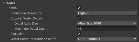
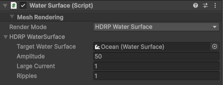
The displacement and flowmapping of the Fluid Simulation is applied using the Water Decal system, which is automatically created when setting the Water Surface to the HDRP Water System mode. The Water Decal system uses signed normalized render buffers to apply the displacement, which requires a amplitude to be applied to the decal. This amplitude is the maximum height the simulation will be able to displace the water surface.
| Property | Description |
|---|---|
| Target Water Surface | The target HDRP Water System component the simulation is to be applied. (Requires HDRP package). |
| Amplitude | Controls the maximum amplitude of the Fluid Simulation used to encode/decode the height to/from 0-1 range |
| Large Current | Controls the weight that the Fluid Simulation’s velocity should be applied to the Large Current waves of the HDRP Water System. |
| Ripples | Controls the weight that the Fluid Simulation’s velocity should be applied to the Rupples of the HDRP Water System. |